CaO Al2O3Si2(s)+ 8C(s) + 8Cl2(g)
= 2AlCl3(g) + CaCl2(s) + 2SikCl4(g) + 8CO(g)
Slag is easily extracted since it is the only solid among the products of this reaction.
Extraterrestrial Fiberglass Production Using Solar Energy
DARWIN HO and LEON E. SOBON
A conceptual design is presented for fiberglass production systems in both lunar and space environments. The raw material, of lunar origin, will be plagioclase concentrate, high silica content slag, and calcium oxide. Glass will be melted by solar energy. The multifurnace in the lunar plant and the spinning cylinder in the space plant are unique design features. Furnace design appears to be the most critical element in optimizing system performance. A conservative estimate of the total power generated by solar concentrators is 1880 kW,- the mass of both plants is 120 tons. The systems will reproduce about 90 times their total mass in fiberglass in 1 year. A new design concept would be necessary if glass rods were produced in space.
INTRODUCTION SOURCES OF RAW MATERIALS
Fiberglass is an ideal material for use in space construction: It can be used for weaving cylindrical mass-driver containers (ref. 1) and for electrical insulation, and for manufacturing many lunar and space structural components such as reinforced plastic structural panels, large fiberglass cylinders, and small-diameter tubing for struts. The more desirable properties of fiberglass are (ref. 2):
SOURCES OF RAW MATERIALS
Fiberglass can be produced from materials available from lunar soil directly and from by-products of aluminum and titanium extractions:
CaOAl2O3Si2(s)+ 8C(s) + 8Cl2(g)
= 2AlCl3(g) + CaCl2(s) + 2SikCl4(g) + 8CO(g)
Slag is easily extracted since it is the only solid among the products of this reaction.
 Ca(s) + Cl2 (g)2CaO(s) + Ti(s)
The approximate fiberglass composition (by weight) to be used is 82-percent slag, 16-percent CaO, and 2-percent anorthite (fig. 1). Since the composition can be varied to obtain fiberglass with different properties and since the chemical quality of the slag and anorthite may vary, chemical analysis must be made to determine the exact weight percentage of each material before mixing After mixing, the material could be ground into finer grains of similar size. This would minimize the melting time.
According to an analysis of the lunar material extraction process (ref. 4), one unit of lunar soil may yield 0.59 unit of material suitable for fiberglass production. Therefore, for a projected annual processing rate of 5.5X 10⁸ kg (600,000 tons) of lunar soil, 3.2X 10⁸ kg (350,000 tons) of material for fiberglass production may be obtained. This amount is more than adequate for a throughput of 9.1 X 10⁶ kg (10,000 tons) of fiberglass per year - the estimated need for the initial buildup of lunar and space bases. The remainder of the yearly slag production would be used to produce shielding material and silicon.
DESIGN OF FIBERGLASS PRODUCTION PLANT
Lunar Plant
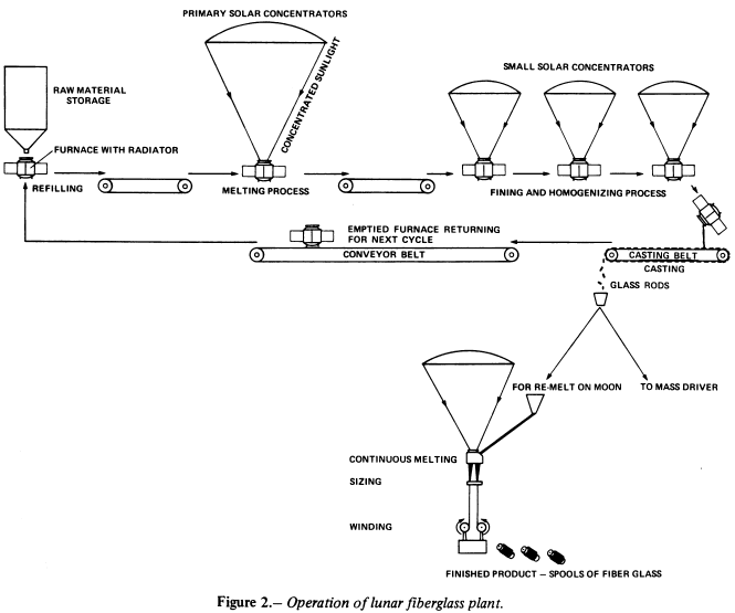
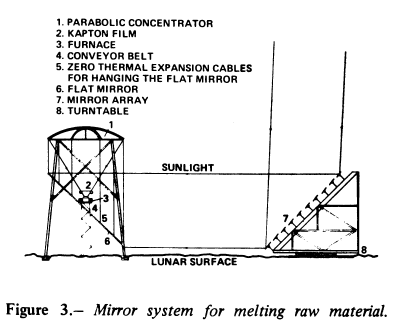
Figure 2 is a schematic diagram of major components of the fiberglass plant. The unique features of this design are that several small furnaces are used and parabolic solar concentrators are installed horizontally pointing down to the lunar surface (fig.3) for convenience in handling molten material (ref. 5). Production of bubble-free glass for continuous filament drawing - The raw material is first melted in a small furnace by the primary solar concentrator. The batch of molten glass is then transferred by conveyor belts to a smaller solar concentrator for fining and homogenizing. (Fining is defined as the minimum heating time to obtain bubble-free, inclusion-free glass.) This two-step procedure is used because the power for fining and homogenizing is only about 30 percent of that required for melting, and fining and homogenizing are time-consuming processes (ref. 6). Therefore, it is preferable to use several smaller solar concentrators for fining and homogenizing so that the primary concentrator can be used full time to melt raw material. The number of small concentrators is described by:
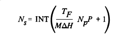
| Ns | number of small concentrators |
| Np | number of primary concentrators |
 H H | enthalpy for fiberglass production (~ 1340 kW-sec/kg) |
| INT | Integer function |
| M | capacity of furnace, kg |
| P | power of primary concentrator, kW |
| TF | time for fining and homogenizing |
There will be a furnace under each concentrator at all times. Therefore, the total number of furnaces required would be the total number of concentrators plus the number of furnaces on the conveyor belt and those for preparing the material for the next cycle.
After the fining and homogenizing are completed, the molten glass is poured into molds that can be of any desired shape (one rod-shaped mold to make a product suitable for shipment to the space manufacturing facility (SMF) by the lunar mass driver). The emptied furnace is then sent back for reloading, thereby preparing the furnace for the next cycle. With this multifurnace technique, maximum productivity is achieved with minimum plant mass.
Re melting and mechanical drawing for making continuous textile filaments- Glass marbles or rods are fed into and melted continuously in another solar furnace. Fiberizing elements (bushings) made of platinum plate with orifices, from which filaments are drawn, are installed in the bottom of this furnace. To lubricate individual filaments and to gather them into continuous and untwisted strands, the filaments are sized below the bushing. From the sizing applicator, each strand is wound onto a forming tube by winder that rotates at a rate up to 4 km/min (refs. 7,8).
Glass Production in the Space Manufacturing Facilities
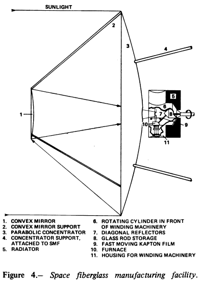
Simulated gravity must be present to handle the molten material in a space furnace. Thus, centrifugal acceleration produced in a rotating cylinder is required. As shown in figure 4, two furnaces are located opposite each other inside a rotating cylinder. The parabolic concentrator is always oriented toward the Sun. Concentrated sunlight is reflected back to the concentrator by a secondary convex mirror and then to the furnaces by a pair of flat diagonal reflectors. These reflectors can be made of highly polished aluminum, coated on the back with carbon black to dissipate absorbed heat. Winding machines similar to those used on the Moon are positioned under each furnace outside the cylinder. These systems will be automated, but minimum manpower will be required for maintenance. For the comparable lunar plant, maintenance will be required at the beginning of each lunar day to begin the drawing process.
MAJOR COMPONENT DESIGNS
Optical System
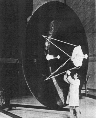
Parabolic collector- Aluminum honeycomb with an aluminum-coated graphite-epoxy skin was selected for construction of the collector because it is lightweight (0.6 kg/m2 for a thickness of 0.064m). The technique for manufacturing the honeycomb structure would be similar to that used to mold the MJS 77 spacecraft high-gain antenna (fig.5 Lightweight honeycomb-graphite/epoxy structure for MJS 77 high gain antenna, photo courtesy of Ford Aerospace.), except the collector will have a much smoother reflecting surface made in small segments that can be assembled in space. The focal length, diameter of the concentrator, diameter of the solar image at the focal plane, weight of the concentrator, and the maximum attainable temperature are described by (ref.9)
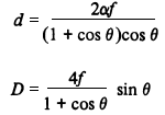
where
| A | external surface of furnace, m2 |
| Ca | concentration ratio = (4F/ 2)sin2 2)sin2 , dimensionless , dimensionless |
| D | diameter of concentrator, m |
| d | diameter of solar image at focal plane, m |
| e | emissivity of external surface of furnace, dimensionless |
| F | efficiency of optical system, dimensionless |
| f | focal length of concentrator, m |
| H | enthalpy for fiberglass production ( 1340 kW-sec/kg) 1340 kW-sec/kg) |
| K | Stefan-Boltzmann constant (5.67X10⁻¹¹ kW/m2) |
| m | production rate, kg/sec |
| T | maximum attainable temperature in furnace, K |
| WW | weight of concentrator, kg |
| w | weight of honeycomb-graphite/epoxy structure per unit area, kg/m2) |
| angular diameter of Sun's disk (0.00931 rad) |
| concentrator rim angle, deg |
 o o | total solar radiation received at normal incidence outside atmosphere (1.394 kW/m2) |
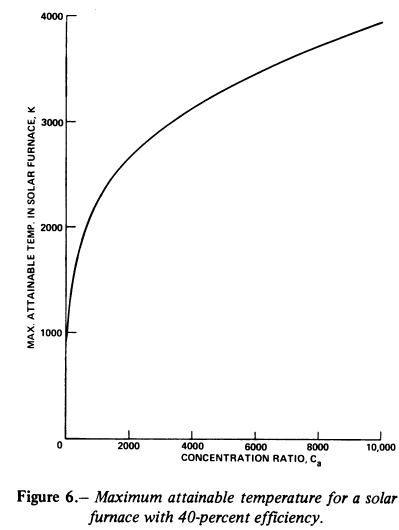
Figure 6 shows the relation between maximum attainable temperature T and concentration ratio Ca.
From this curve, note that the concentration ratio Ca should be no less than 427.0 or, in other words, the rim angle cannot be less than 8.8o to maintain a furnace temperature of 1800 K, which is required to melt glass. Ca and should be greater than 650.8 and 10.6o , respectively, for a furnace temperature at 2000 K, which is required for fining and homogenizing. For heat flux control, shutters will be used.
Flat mirror and heliostat- Aluminum-coated Kapton film stretched on a lightweight structure was chosen as the reflecting surface for minimum weight. Figure 3 shows the plane mirror of the heliostat divided into several bands to eliminate the distortion of a large single frame as it changes position during Sun-tracking. These bands may be constructed on a pyramid like structure that rests on a rotating disk.
Furnace Design
The time required for fining and homogenizing (exact time determined by experiment) increases exponentially with the mass of the molten glass: the number of concentrators required for fining would be increased exponentially. Therefore, a small furnace cavity is chosen to minimize the number of concentrators and thus increase the annual throughput/plant-mass ratio. For example, a volume of 0.1 m3 has a capacity of 90 kg of raw material, which requires roughly 2.6 min for melting and 30 min for fining and homogenizing.
The cavity paving is a heat-resistant refractory material such as zircon
(note:mullite 3Al2O32SiO2 . which can be produced from lunar resources may be used as a substitute for zircon (which cannot be readily produced from lunar material). However, there is a potential problem that mullite may dissolve into molten glass and thus affect the glass properties). To minimize the corrosion caused by the molten glass, the coils attached to the outer surface of the paving will be turned on after all raw material has melted, thus forming a protective solid glass layer adjacent to the zircon. The paving should be at least 10 cm thick for a reasonable lifetime of several years. The paving is surrounded by a thick layer of lunar soil (up to 1 m thick) to reduce energy loss due to radiation (fig. 7). The power requirement for fining and homogenizing is expressed by
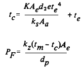
where
| Aa | mean area between paving and external surface of furnace, m2 |
| Ae | external surface of furnace, m2 |
| dp | thickness of paving, m |
| ds | thickness of lunar soil, m |
| ks | conductivity of packed lunar soil; ~ 2.09X10⁻³ kW/mK |
| kz | conductivity of zircon; ~ 2.93X10⁻³ kW/mK |
| PF | power requirement for fining and homogenizing kW |
| tc | temperature of cooling coil, K |
Contamination of the concentrator and diagonal reflector surface by vapor from the glass-melting process can be eliminated by having transparent Kapton film moving above each furnace (ref. 10). A similar furnace could be used to melt glass rods. In this furnace, however, platinum bushings are inserted on the bottom of the furnace, and glass rods are fed in continuously.
Dimensions of the System
To meet the projected fiberglass throughput of 9.1X 10³ kg (10,000 tons) per year, the lunar plant will produce 0.58 kg of glass rods per second (780 tons/lunar day). One-tenth of these will be processed into fiberglass on the Moon and the rest will be processed at the SMF. If the capacity of the furnace is chosen to be 0.1 m3 , the thickness of the insulating lunar soil is 0.5 m (the estimated mass of each furnace is about 2.7X10³ kg); if four primary solar concentrators are used on the lunar plant, then the power requirements, concentrator characteristics, and mass of the plants would be as summarized in tables 1, 2, and 3. Since the total mass of the system is about 110X103 kg (120 tons), it will be able to process raw material about 90 times its own mass in 1 year.
| Process | Production rate, kg/sec | Power required, kW |
| Melting raw material | 0.58 | 820 |
| Fining and homogenizing | .58 | 240 |
| Remelting glass rods on Moon | .06 | 80 |
| Remelting glass rods at SMF | .52 | 740 |
| Process | NUmber of concentrators | Mass kg/unit | Diameter, m | Power output, kW/unit |
| For melting raw material | 4 | 350 | 26.5 | 205 |
| For fining and homogenizing | 12 | 20 | 6.6 | 20 |
| For remelting glass rods on Moon | 1 | 135 | 16.5 | 80 |
| For remelting glass rods at SMF | 1 | 1520 | 55 | 740 |
| Equipment | Lunar plant mass, 10 | SMF plant mass, 10 |
| Mirrors and support structure | 20 | 3 |
| Furnaces 24 on Moon 2 at SMF | 65 | 5.4 |
| Winding and auxiliary machinery Conveyor belt | 7 | - |
| Total weight | 97 | 14.4 |
CONCLUSIONS
Abundant amounts of fiberglass can be produced from lunar materials. The key factors in designing the production plants are system mass optimization, technological availability, and highly automated operations. It has been chosen that glass rods will be produced on the Moon. However, if all lunar raw materials are processed at the SMF, a different system should be designed to produce glass marbles in space. The SMF plant may have a higher production rate/plant-mass ratio since sun light is available at all times in space. The design of the furnace appears to have the strongest effect on system performance, and further research must be done. Other recommended areas for further study include:
|
Curator: Al Globus If you find any errors on this page contact Al Globus. |
 |
This site was hosted by the NASA Ames Research Center from 1994-2018 and is now hosted by:
