The baseline lunar material transportation system involves a magnetically levitated vehicle, or "bucket," accelerated by a linear synchronous motor. Acceleration is at 288 m/s^2 along l0 km of track. The bucket is accelerated through use of superconducting magnets at 3T; bucket mass is under 10 kg.
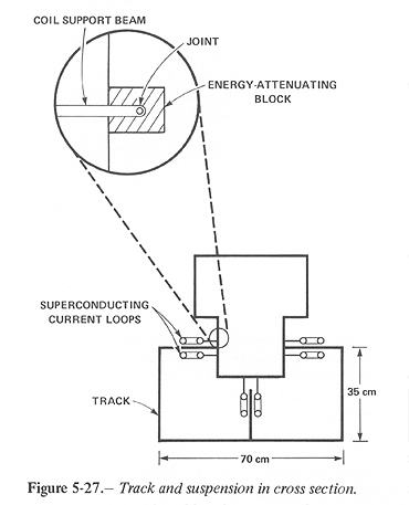
The suspension and control of motion required to implement the launch with a velocity error under 10^-3 m/s are accomplished by a passive control system. The bucket and suspension are shown schematically in figure 5-27.
The suspension involves paired magnetic coils, coupled mechanically to the bucket through an attachment which provides elastic suspension and damping by an energy-attenuating block made of a rubber-like material.
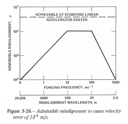
Figure 5-28 shows the frequency response of this system due to excitation. At 2400 m/s the range of misalignment wavelengths of 24 to 240 m gives the most severe response. Within that wavelength range misalignments cannot exceed 0.01 cm for the induced velocity not to exceed 10^-3 rn/s. At longer and at shorter wavelengths, more severe misalignments can be tolerated; for example, up to 0.1 cm at 2400 m.
Electromagnetic "bumpiness" deserves attention. This occurs with a wavelength of approximately 1 m, that is at 2400 Hz, due to use of discrete segments of accelerating coils on the linear synchronous motor. The maximum acceleration is proportional to the maximum angle of the bucket; if the bucket pitches down by 0.01 rad, the acceleration normal to the track is 3 m/s^2. The resulting velocity normal to the track is of amplitude 1.25 X 10^-3 m/s. A tight suspension, incapable of sustaining large angular deflections in the bucket, reduces the bumpiness-induced oscillations to within desired limits. During a phase of drift, or of electromagnetic acceleration at low levels, the bumpiness may be reduced by orders of magnitude. Track misalignment and distortions, rather than electromagnetic bumpiness, are the major source of residual velocity error.
Track Alignment
Three methods of track alignment might be considered.
 .
.Launch Sequence
The launch sequence as a bucket proceeds along the track might be described as follows:
Payload Restraint System
The payload may be of sintered lunar material, resembling a cinder block. This block is rigidly held in place by trapezoidal restraints fitted to the sides of the block. These restraints are pin-secured and spring-loaded; pulling the pins causes the restraints to spring back. A final restraint, however, continues to press down on the block from above; this restraint may function as a mechanical "finger." This holds the block down during the fine acceleration and drift phases.
The track may be contoured to the lunar curvature, so that the block feels an upward acceleration, at escape velocity, of one lunar gravity (1.5 m/s^2). Thus, when the restraint is rapidly pulled away, the block drifts free. There is a spring effect due to the block having been compressed slightly by the restraint, with strain energy being stored in the block and converted to kinetic energy upon release. This effect leads to velocity errors at release of less than 10^-5 m/s.
Track
The track cross section is shown in figure 5-27. This geometry was selected purely
because it is convenient for a typical bucket; it is a conservative
design in that a section of equal mass can be given greater
stiffness. The section is of aluminum: density  g/cm^3, modulus of elasticity E=7 X 10^1l dynes/cm^2,
and momnent of inertia I = 40,350 cm^4 for t = thickness in cm.
g/cm^3, modulus of elasticity E=7 X 10^1l dynes/cm^2,
and momnent of inertia I = 40,350 cm^4 for t = thickness in cm.
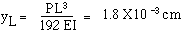
The track is laid on supports in such a manner that the sag
under its own weight, between the supports, is under 10^-2 cm. At
the supports, optical measurement equipment together with screw
jacks permit accurate alignment of a straight track. The sag is
given by the formula for sag  of a
uniformly-loaded beam with ends clamped or built-in, a condition
which is met by the beam being horizontal at the supports. This
formula is
of a
uniformly-loaded beam with ends clamped or built-in, a condition
which is met by the beam being horizontal at the supports. This
formula is

where L = distance between supports, W = weight per unit length
= (540 t g/cm) X (150 cm/s^2) = 0.81 N/m of length. Then, with L=
103 cm = 10 m,  = 7.5 X l0^-3 cm.
This is well within the misalignment permitted by figure 5-28.
= 7.5 X l0^-3 cm.
This is well within the misalignment permitted by figure 5-28.
The bucket has negative weight (since it is travelling at lunar
escape velocity) and hence causes the beam to bend upward. The
bucket has mass, say, of 30 kg; its weight is approximately 50 N.
The resulting maximum static deflection  is:
is:
for t = 0.5 cm. A design with t = 0.5 cm appears to offer adequate strength and rigidity.
The track mass is 27 kg/m of length. If shipped in lengths of 30m, 1671engths (5000 m) approximately fill an HLLV payload bay, > 30 m long X 8.41 m diameter, allowed mass = 135,000 kg. All allowed mass is used while efficiently filling the available volume.
The free beams oscillate with frequency near 100 Hz and
amplitude under  < = 3.6X10^-3 cm,
so the associated transverse velocity is 3.6 X l0^-3 cm/s. But
figure 5-28 shows that this input is
attenuated by an order of magnitude in the bucket so that it is
well within allowed limits, 0.l cm/s at the bucket.
< = 3.6X10^-3 cm,
so the associated transverse velocity is 3.6 X l0^-3 cm/s. But
figure 5-28 shows that this input is
attenuated by an order of magnitude in the bucket so that it is
well within allowed limits, 0.l cm/s at the bucket.
Mass Driver Throughput
Maximum throughput for a mass driver track, given a payload mass, appears to be constrained by payload spacing and by energy dissipation. Neither of these constraints appears to prevent throughputs greatly in excess of those in the baseline system.
As a linear synchronous motor, the mass driver permits discrete, accurate control of bucket locations. Separation of buckets should be maintainable so long as each is handled by a separate driven section. At two driven sections per bucket, 2 m per driven section, 1 km/s velocity, and 10kg per bucket, maximum throughput would be 2500 kg/s. Since over 80 percent of the track operates at more than 1 km/s, special construction of the remaining 20 percent should add little cost. Possibilities include shorter driven segments to permit closer payload spacing or parallel feeder tracks interleaving payloads onto the main section.
An acceleration of 300 m/s^2 adds 300 J/kg for each meter of track. At 70 percent conversion efficiency, this deposits almost 130 J/(kg m); at the limit of 2500 kg/s this represents a heat load of 3.2 X 10^5 W for each meter of track. This, in turn, would require a radiator along the track some 300 m wide, if at the boiling point of water. Because much of this energy is lost to resistance in the bus and feeder conductors, these could be made of aluminum, thickened to reduce resistance, and made broad to serve as structural elements as well as self-cooling radiators. Such a system would reduce the need for active cooling.
|
Curator: Al Globus If you find any errors on this page contact Al Globus. |
 |
This site was hosted by the NASA Ames Research Center from 1994-2018 and is now hosted by: